SETTING THE SWR OF YOUR ANTENNAPLUS NEW SPECIAL SECTION ON COAX CABLE
PROCESSING Firestik®; Antenna Co. Technical Support | |||||||||||||||||||||||
 |

|
|
|---|---|---|


 Leave a Message by Email |
|
800 889 2839 or 800 889 2839 Hours: 8:00 AM - 8:00 PM We do not accept credit cards from outside the USA and Canada
|
|---|

Contents of this Page
Setting the SWR of Your Antenna
Coax Cable Processing with Firestik Connectors

SETTING THE SWR OF YOUR ANTENNA
SWR (standing wave ratio), is a measurement of how efficiently your antenna system will radiate the power available from your radio. In simple terms, your radio would like to radiate all of its power, but can only do so if the other components cooperate. Bad coax and mounts, or inefficient antennas and ground plane can cause system bottlenecks. The easiest way to understand the concept is to think of it in terms of water flow. That is, if you put a one inch faucet on a two inch pipe, your potential output will be restricted by the one inch outlet. So goes antenna systems. Setting your antennas SWR will reduce the restriction of radiated power.
If all radios only transmitted on one channel, it would be a much easier task to design antennas. As it is, on CB alone, there are 40 channels to contend with. Mobile antennas can only be made to resonate at one specific frequency (channel). The goal of the antenna manufacturers is to build the antenna to resonate at a frequency in the middle of the available band (channel 19 on CB) and make it broad- banded enough to keep the off-frequency related SWR at the two extreme ends of the band below 2.0:1. It should be noted that if you communicate on one or two adjacent channels anywhere within the band, you can tune your antenna to achieve optimum performance on those channels. Most people, however, prefer to use the entire bandwidth when tuning.
THINGS YOU WILL NEED
- Knowledge of what not to do .... read previous sections.
- Properly installed antenna system (mount, coax and antenna) that was made for the type of radio you will be using and has been tested for shorts and opens in continuity. (See "Testing Continuity")
- Functional radio.
- SWR meter. (See "SWR Meter Hook-Up")
- Short piece of coaxial cable (jumper) with PL-259 connectors on both end.
SWR METER HOOK-UP
The SWR of the antenna, without feedline, can be measured by placing the SWR meter in-line at the antenna instead of at the radio. However, the coax can help or hinder performance. In the end, your SWR should be checked at the radio end because all components will be a part of the final operational system being used.
SWR TESTING REMINDERS:
- Remember to check for continuity, shorts and opens in your coax and mount installation first.
- Take measurements in an open area with the vehicle's doors and hatches closed.
- All measurements should be taken with antenna tip on, unless you do not plan to use the tip in normal use.
THE SET UP

If already connected, disconnect the coaxial cable from the radio. Connect the coax cable that normally connects to the back of the radio to the SWR meter connector marked "Antenna" or "Ant". Now, connect one end of the jumper cable to the back of the radio and the other end to the SWR meter connection marked "Transmitter" or "Xmit". Your SWR meter is now in series (in-line) with your radio and antenna.
Since you've already read the previous parts of this pamphlet, you should now have your vehicle in an open area, with all doors closed. Turn your radio on and tune to channel one or the lowest channel on your radio. If your radio has side band operation, make sure you are in AM mode before doing SWR tests.
The following assumes that your SWR meter has a standard set of switches, knobs and meters. That is, there will be at least one switch with the marking Forward (FWD) in one position and Reference (REF or SWR) in the other. There will also be a knob or sliding controller marked "Set" or "Adjust". Most meters come with full instructions. If the common configuration does not match your meter you will need to rely on the meters manual for assistance.
With the radio on the lowest channel (1 on CB) and the SWR meters switch in the Forward (FWD) position, depress the transmit switch (key up) located on the microphone. While holding the unit in this transmit mode, adjust the meter needle to the set position using the Set or Adjust knob on the meter. As soon as the needle is in alignment with the corresponding mark on the meter face, flip the switch to the Reference (REF) position. The meter is now showing your SWR on channel one. Note the value and quickly release the microphone switch. Record this reading on your paper to the nearest 1/10th. i.e. 1.8, 2.3, 2.7, 1.4, etc.
Now, switch your radio to the middle channel (19 on CB). Place the meter switch in the Forward (FWD) position, depress the microphone switch and adjust the meter to place the needle on the Set position of the meter face. Once in the set position, place the meter switch in the Reference (REF) position and note the reading. Release the microphone switch and write this value down to the nearest tenth of a point. Note: If your antenna system is closely matched to the radio you may get little or no movement from the meter needle on this channel. This is normal.
Finally, place your radio on the highest number channel (40 on CB). Place the meter switch in the Forward (FWD) position, depress the microphone switch and adjust the meter to place the needle on the Set position of the meter face. Once in the set position, place the meter switch in the Reference (REF) position and note the reading. Release the microphone switch and write this value down to the nearest tenth of a point.
With these three readings, you can determine many things about your system. For instance ...
- If SWR on channels 1, 19 & 40 is below 2.0, your radio can be safely operated on any channel without causing damage to the radio's circuitry.
- If SWR on all channels is above 2.0 but not in the "red zone" (normally over 3.0), you may be experiencing coaxial cable reaction (bad quality, wrong length, etc.), insufficient ground plane, or have an ungrounded antenna mount.
- If SWR is in the "red zone" on all channels, you probably have an electrical short in your coax connectors, or your mounting stud was installed incorrectly and is shorted. DO NOT USE YOUR RADIO UNTIL YOU HAVE FOUND THE PROBLEM.
- If SWR on the lowest channel is higher than it is on the highest channel, your antenna system appears to be electrically short. See the following section title "Adjusting Short Antennas".
ADJUSTING LONG ANTENNAS
If the SWR on channel 40 is greater than that on channel 1, your antenna is considered to be "LONG" and reduction of physical height and/or conductor length will correct this situation. Depending upon antenna model, this entails screwing down the tunable tip (Illustration #1: Firestik II, Firefly), or, removing the tip, making short slits in the plastic covering and unwinding and clipping off wire (Illustration #2: Firestik, Road Pal). Firestik Designer Series antennas require loosening the allen screws and lowering the metal whip (Illustration #3).

ADJUSTING SHORT ANTENNAS
If SWR on channel 1 is greater than that on channel 40, your antenna is considered to be "SHORT" and increasing the physical and/or electrical length of the antenna is required to correct this situation. Because we make our antennas extra long, readings which indicate "Short" normally stem from ground plane deficiency (lack of vehicle metal surface for the antenna to reflect its signal rom). This condition is often corrected by adding a spring and/or quick disconnect to increase the physical height. Ground plane deficiencies can also be compensated for by using dual (co-phased) antennas or special no-ground-plane antenna kits.
Lengthening of the Firestik II and Firefly is accomplished by turning the tuning screw further out (Illustration #1). On Firestik and Road Pal models, it requires tip removal, short slits in the plastic covering and, the separation and upward repositioning of three or more wire turns (Illustration #4). Firestik Designer Series antennas require loosening the allen screws and raising the metal whip (Illustration #3).
NOTE: The shorter the antenna, the more sensitive it is to adjustments. For example, removing two wire turns on a 4 foot antenna might move the SWR by 0.3; the same amount removed from a 2 foot antenna may move the SWR by 1.0. Make smaller adjustments on shorter antennas.
DUAL ANTENNAS
Measurements and determination of short or long conditions are the same as the single antenna procedure. However, when tuning co-phased antennas, if you adjust one antenna, it is advisable to adjust the other in equal amounts to keep them in perfect balance.
COAX CABLE PROCESSING with FIRESTIK CONNECTORS
Using PRO-259 with cable type insert.
Using Twist-On connector (T6-259 or T7-259)
Using Twist-On connector w/ rubber boot
(BT6-259 or BT7-259)
Using CP-259 to build co-phasing harness
THINGS TO KNOW
- RG-58 refers to any RG-58 type cable such as RG-58-U or RG-58-A/U.
- RG-59 refers to any RG-59 type cable such as RG-59-U or RG-59-A/U.
- The "A" designation after RG-58 or RG-59 indicates a stranded center conductor, wire made up of numerous individual strands versus one solid wire.
- RG-58 type coax is 50 ohm cable and is used for single antenna installations of CB, scanner, 2-meter, and 10-meter Firestik antennas. RG-8 and RG-8X are other common coax types that can be used on single antenna installations.
- RG-59 type coax is 72 ohm cable. It is used for dual (co-phased) CB, 2-meter or 10-meter installations. It is also commonly used for TV antennas and AM/FM receive only antennas. Do not use this coax on single CB antenna installations.
- The length, type and quality of the coaxial feedline can have a major effect on system performance. If in doubt, use 18ft coax that has the "A" designation after the RG type.
- The coax used on Firestik "no-ground-plane" kits must never be altered. It's length and internal features are critical to proper operation.
- The shield on "no-ground-plane" kits is intentionally not used at the mount end of the coax. Leave as is.
- The shield portion of the coax cable is almost always used as the ground.

PROCESSING COAX FOR RING/SPADE TERMINALS
- Remove 1" (38 mm) of the cable's protective cover (see Diagram A, next page).
- Use end of nail or other pointed object to unbraid the copper shield. When done, pull to one side and twist into a single wire. Trim off any loose ends.
- Remove 3/8" (10 mm) of the center conductor insulation and dress by twisting strands into one wire.
- If soldering equipment is available, tin the ends of both wires.
- If shrink tubing will be used for additional insulation, slide over wire end(s) at this time.
- Crimp and/or solder terminal(s) to appropriate wire. In most cases, the larger of the two terminals will go on the center conductor. If both terminals are the same size but one has it's own insulation, this should be used on the center conductor.
- If shrink tubing was used, slip it over the terminal end and heat until properly fitted.
- Test your work for opens or shorts (see "Testing Continuity").

INSTALLING PRO-259 WITH CABLE INSERT
NOTE: Soldering iron and solder required for this connector.
- Slide appropriate cable adapter over coax, INS-58 for RG58 cable or INS-59 for RG59 or RG8X cable. Make sure wide shoulder is down, threaded portion up (see Diagram B).
- Remove (unscrew) PRO-259 knurled barrel sleeve from main connector and drop over coax. Make sure that the internal threads are up.
- Remove 1" (25 mm) of the cables outer cover.
- Use end of nail or other pointed object to unbraid the copper shield. Trim to approximately 1/2" (12mm) long all the way around.
- Remove 1/2" ( 12 mm) of the center conductor insulation and dress by twisting all strands into one wire.
- Use your soldering iron to tin the end of the center conductor wire.
- Slide the insert up the cable until the top is even with the trimmed edge of the outer cover. Fold the braided shield over the top of the insert. Make sure the wire does not lay in the treads of the insert. If the braid is a little long, twisting the braid around the insert will keep it out of the threads.
- Thread the main connector body on to the cable insert until fully seated. Locate shield through one or more holes in main body. Heat body and shield at one or more access holes and fill with solder.
- Solder center conductor where it protrudes from center pin of main body. Do not over fill or pin will be to fat to fit into mating connector. Trim off any excess wire.
- Slide the knurled barrel up the cable and re-thread to the main body.
- Test your work for opens or shorts (see "Testing Continuity").

INSTALLING T6-259 OR T7-259 TWIST-ON CONNECTOR
Note: Soldering iron and solder required for this connector.
- Select appropriate connector for cable type, T6 for RG-58 or T7 for RG-59 coax.
- Remove (unscrew) knurled barrel sleeve from main connector and drop over coax. Make sure that the internal threads are up (see Diagram C).
- Remove 1" ( 25 mm) of cables outer cover.
- Use end of nail or other pointed object to unbraid the copper shield. Trim to approximately 3/8" (10mm) long all the way around.
- Remove 1/2" ( 12 mm) of the center conductor insulation and dress by twisting all strands into one wire.
- Use your soldering iron to tin the end of the center conductor wire.
- Fold the braided shield down over the top of the outer cover.
- Thread the main connector body on to the cable until fully seated or the center conductor is at the end of the main body center pin.
- Solder center conductor where it protrudes from center pin of main body. Do not over fill or pin will be to fat to fit into mating connector. Trim off any excess wire.
- Slide the knurled barrel up the cable and re-thread to the main body.
- Test your work for opens or shorts (see "Testing Continuity").

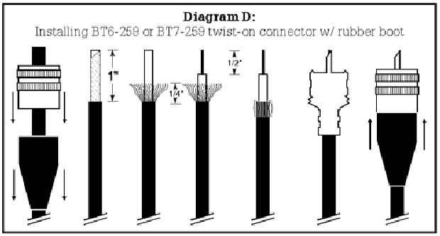
INSTALLING BT6-259 OR BT7-259 TWIST-ON CONNECTOR W/ RUBBER
BOOT
Note: Soldering iron and solder required for this connector.
- Select appropriate connector for cable type, BT6 for RG-58 or BT7 for RG-59 coax.
- Slide rubber boot over cable with large opening up.
- Remove (unscrew) knurled barrel sleeve from main connector and drop over coax. Make sure that the internal threads are up (see Diagram D).
- Remove 1" (25 mm) of cables outer cover.
- Use end of nail or other pointed object to unbraid the copper shield. Trim to approximately 1/4" (6mm) long all the way around.
- Remove 1/2" (12 mm) of the center conductor insulation and dress by twisting all strands into one wire.
- Use your soldering iron to tin the end of the center conductor wire.
- Fold the braided shield down over the top of the outer cover.
- Thread the main connector body on to the cable until fully seated or the center conductor is at the end of the main body center pin.
- Solder center conductor where it protrudes from center pin of main body. Do not over fill or pin will be to fat to fit into mating connector. Trim off any excess wire.
- Slide the knurled barrel up the cable and re-thread to the main body.
- Slide rubber boot up cable and snap over the main body (2 clicks)
- Test your work for opens or shorts (see "Testing Continuity").
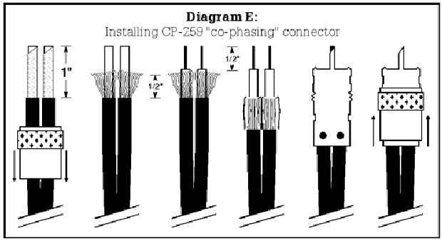
INSTALLING CP-259 "CO-PHASING HARNESS" CONNECTOR
Note: Soldering iron and solder required for this connector.
- Remove (unscrew) knurled barrel sleeve from main connector and drop over both pieces of coax. Make sure that the internal threads are up (see Diagram E).
- Remove 1" (25 mm) of both cables outer cover.
- Use end of nail or other pointed object to unbraid the copper shield. Trim to approximately 1/2" (12mm) long all the way around.
- Remove 1/2" (12 mm) of the center conductor insulation from both cables and dress each by twisting all strands together.
- Use your soldering iron and lightly tin the ends of both center conductor wires.
- Fold the braided shield down over the top of the outer cover on both cables.
- Insert each cable into the connector body making sure the center conductor protrudes from the body center pin.
- Solder center conductor where it protrudes from center pin of main body. Do not over fill or pin will be to fat to fit into mating connector. Trim off any excess wire.
- Solder the shield on both cables to the main body using the corresponding access hole.
- Slide the knurled barrel up the cable and re-thread to the main body.
- Test your work for opens or shorts (see "Testing Continuity").
NOTE: If you will be using grommets to protect your cable where it passes through the vehicle body, make sure the grommets are on the cable before processing connector(s).
Firestik® Antenna Company manufactures a complete line of antennas and accessories for CB, scanner and amateur radio equipment.write to:
Po Box 116
Eureka, Montana
(59917)
(e-mail) pstramer@eurekadsl.net
or call:
(tel/fax) 800 889 2839
406 889 3183
SLC Distributing TECHNICAL SUPPORT HELP LINE: 1-406 889 3183
SWR Testing of Mobile Transmit Antennas